
Equipment
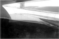
Results are presented from a towing-tank experiment conducted in order to explicate the influence of wavemaking by a surface-piercing body on its boundary layer and wake and provide detailed documentation of the complete flow field appropriate for validating computational fluid dynamics methods. Mean velocity and pressure field measurements were performed for two Froude numbers, 0.16 and 0.316, for the L=3.048-m Series 60 CB=0.6 hull form at numerous stations from bow to stern and into the near wake. For Froude number=0.316, free surface effects are very significant, whereas for Froude number=0.16, they are negligible, except near the bow, such that comparison of the results enables the identification of the salient features of the wave-induced effects. Wave profiles and nearfield and farfield wave elevations were also measured. In addition, resistance tests were conducted. In the references below, the experimental equipment and procedures are described and the results are discussed to point out the essential differences between the flows at low and high Froude number. On the forebody, the differences are primarily in the outer (inviscid) flow, except at the bow, whereas on the afterbody and in the near wake, both the inner (viscous) and outer flows are altered. Most of the interaction between wavemaking and the boundary layer and wake can be explicated as a result of the wave elevations, wave-induced pressure gradients, and the displacement effects of the boundary layer.
Data, Equipment, and Conditions
| Data | Equipment | Fr | Locations |
| Resistance | 20 kg loadcell | 0.1-0.36 | – |
| Wave profiles | 35 mm camera | 0.25, 0.3, 0.316 | |
| Far field wave elevations | Capacitance wires | 0.316 | |
| Near field wave elevations | Servo-type wave gage | 0.316 | |
| Boundary layer and wake flow field | 5-hole pitot probe and pressure transducers | 0.16, 0.316 | x / L = 0, 0.1, 0.2, 0.4, 0.6, 0.8, 0.9, 1.0, 1.1, 1.2, y / L = 0-0.03, z / L = -0.125-0 |
Sample Data
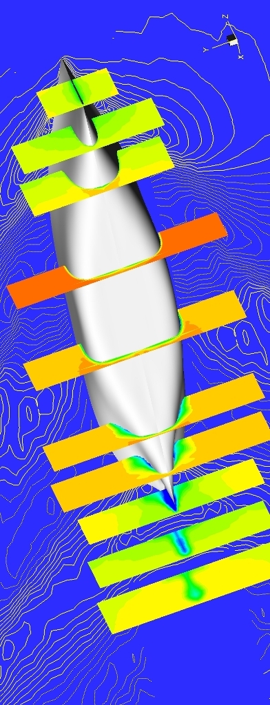
Flow field contours of axial velocity U at x = 0, 0.1, 0.2, 0.4, 0.6, 0.8, 0.9, 1.0, 1.1, 1.2 (foreground) and wave field contours (background) for the Series 60CB = 0.6 at Fr = 0.316.
References:
Longo, J., (1990), “Scale Effects on Near-Field Wave Patterns,” M.S. thesis, Department of Mechanical Engineering, The University of Iowa, Iowa City, IA., 141 pp.
Longo, J., Stern, F., and Toda, Y., (1993), “Mean-Flow Measurements in the Boundary Layer and Wake and Wave Field of a Series 60 CB=0.60 Ship Model – Part 2: Scale Effects on Near-Field Wave Patterns and Comparisons with Inviscid Theory,” Journal of Ship Research, Vol. 37, No. 1, pp. 16-24.
Toda, Y., Stern, F., and Longo, J., (1991), “Mean-Flow Measurements in the Boundary Layer and Wake and Wave Field of a Series 60 CB=0.6 Ship Model for Froude Numbers 0.16 and 0.316,” IIHR Report No. 352, 188 pp
Toda, Y., Stern, F., and Longo, J., (1992), “Mean-Flow Measurements in the Boundary Layer and Wake and Wave Field of a Series 60 CB=0.6 Ship Model – Part 1: Froude Numbers 0.16 and 0.316,” J. of Ship Research, Vol. 36, No. 4, pp. 360-377.