
Experiment

Results are presented from a towing-tank experiment of propeller-hull interaction conducted in order to provide detailed documentation of the complete flow field appropriate both for explicating the flow physics and validating computational methods. Mean-velocity and pressure field measurements were made for the with- and without-propeller conditions for the Series 60 CB=0.6 hull form at numerous stations both upstream and downstream of the propeller and in the near wake region. Surface-pressure distributions and wave profiles were measured for both conditions. Resistance and self-propulsion tests were also conducted. In the references below, the experimental equipment and procedures are described, and the results are discussed to point out the essential differences between the flow with and without propeller. The results are analyzed to assess the nature of the interaction between the propeller and the hull boundary layer and wake. To this end, use is made of a propeller-performance program with both nominal and effective inflows. It is shown that most features of the interaction can be explained as a direct consequence of the propeller loading resulting from its operation with a three-dimensional nonuniform inflow.
Data, Equipment, and Conditions
| Data | Equipment | Fr | KT, KQ, J | Locations |
| Resistance | Dynamometer | 0.08-0.27 | – | – |
| Propeller open water | Dynamometer | 0.10-0.36 | – | – |
| Self propulsion | Dynamometer | 0.08-0.27 | – | – |
| Wave profiles | 35 mm camera | 0.16, 0.25, 0.30, 0.35 | – | |
| Surface pressure | Pressure transducers | 0.16 | 0.234, 0.0411, 0.654 | |
| Boundary layer and wake flow field | 5-hole pitot probe and pressure transducers | 0.16 | 0.234, 0.0411, 0.654 | x / L = 0, 0.1, 0.2, 0.4, 0.6, 0.8, 0.9, 1.0, 1.1, 1.2, y / L= 0-0.03, z / L = -0.125-0 |
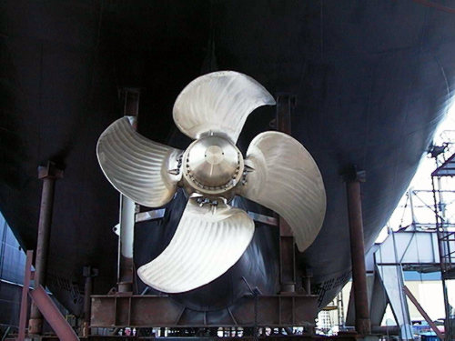
Sample Photo
Sample Data
Surface pressures (Cp) at x = 0.95 (red), x = 0.9625 (green), and x = 0.975 (blue) for the with-propeller condition.

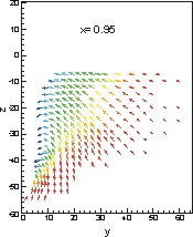
Crossflow vectors (V, W) at x = 0.95 for the with-propeller condition.
References:
Toda, Y., Stern, F., Tanaka, I., and Patel, V.C., (1988), “Mean-flow measurements in the boundary layer and wake of a Series 60 CB=0.6 model ship with and without propeller,” IIHR Report No. 326, 100 pp.
Toda, Y., Stern, F., Tanaka, I., and Patel, V.C., (1988), “Mean-flow measurements in the boundary layer and wake of a Series 60 CB=0.6 model ship with and without propeller,” J. Ship Research, Vol. 34, No. 4, pp. 225-252.