
Image of model ship moving through water
Experiment
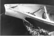
Yaw effects on model-scale ship flow are documented through towing-tank experiments for a 3.048-m Series 60 CB=0.6 model ship. The data includes: photographs and video; resistance, side force, and yaw moment; sinkage, trim, and heel; wave profiles along the hull and wave elevations; and mean-velocity and pressure fields for numerous crossplanes from the bow to the near wake. Comparison of results for low (0.16) and high (0.316) Froude number with those from an earlier study for the without-yaw condition enables identification of the salient yaw- and wave-induced effects. The forces, yaw moment, and displacements increase significantly with increasing yaw angle. The wave pattern is asymmetric with increased/decreased Kelvin angle, wave lengths, and amplitudes on the windward/leeward sides, respectively. Close to the hull, the differences are confined to the bow, whereas away from the hull the differences are throughout the measurement region, i.e., nearfield. The mean-velocity and pressure fields are dominated by strong crossflow effects, including forebody and afterbody keel and bilge vortices. A wave-induced vortex is exhibited for high Froude number. The similarities and differences between the present results and analysis from related studies are discussed. The results should be useful for computational fluid dynamics validation.
Data, Equipment, and Conditions
| Data | Equipment | Fr | Drift angle b | Locations |
| Resistance | 20 kg loadcell | 0.1-0.36 | 0, 2.5, 5.0, 7.5, 10 | – |
| Wave profiles | 35 mm camera | 0.25, 0.3, 0.316 | 0, 5, 10 | |
| Far field wave elevations | Capacitance wires | 0.316 | 0, 5, 10 | |
| Near field wave elevations | Servo-type wave gage | 0.316 | 0, 5, 10 | |
| Boundary layer and wake flow field | 5-hole pitot probe and pressure transducers | 0.16, 0.316 | 10 | x / L = 0, 0.1, 0.2, 0.4, 0.6, 0.8, 0.9, 1.0, 1.1, 1.2, y / L= 0-0.03, z / L = -0.125-0 |
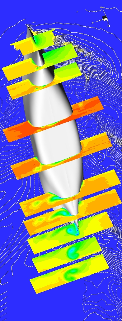
Sample Data
Flow field contours of axial velocity U at x = 0, 0.1, 0.2, 0.4, 0.6, 0.8, 0.9, 1.0, 1.1, 1.2 (foreground) and wave field contours (background) for the Series 60CB = 0.6 at Fr = 0.316 and a drift angle b = 10°.
References:
Longo, J., (1996), “Effects of Yaw on Model-Scale Ship Flows,” Ph.D. thesis, Department of Mechanical Engineering, The University of Iowa, Iowa City, IA., 275 pp.
Longo, J. and Stern, F., (2002), “Effects of drift angle on model ship flow,” Experiments in Fluids, Vol. 32, pp. 558-569.